I’ve always thought that at a CNC milling machine is the ultimate tool for any workshop. While most of us don’t have the space or budget for one, I can probably find room for the next best thing, a small CNC router. I knew this was something I could build myself, on a fairly tight budget. I wanted my machine to be as accurate and repeatable as possible with a 12″ x 12″ work area. My main intent is to do isolation milling to 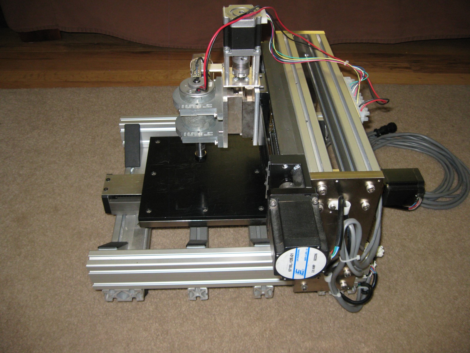 make circuit boards and to cut out thin plastic parts.
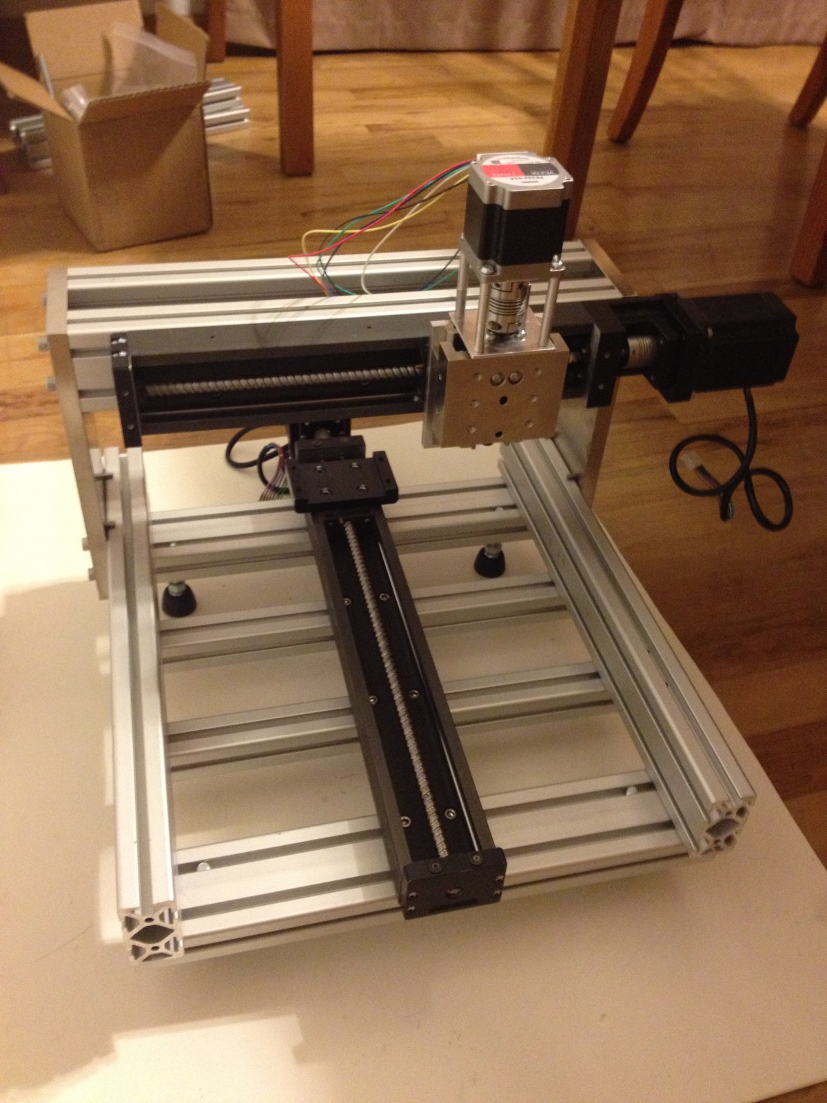
I started to do some research, and found that there were quite a few open source machine designs and software options available. I quickly decided to use the Arduino based GRBL, because it had a lot of support and I was already familiar with Arduino, which would accelerate the learning curve for this project. I started out with a solid professional understanding of motion control systems for robotics, but  didn’t know anything about CNC or CAM software. None of the open source machines designs appealed much to me, so I went to ebay to look for inexpensive linear motion components and some inspiration. I found a very reasonably priced set of name brand integrated ball screw actuators that would be great for the x- and y-axes, and give me the accuracy I was looking for, so I hit the “Buy It Now” button and began the mechanical design.
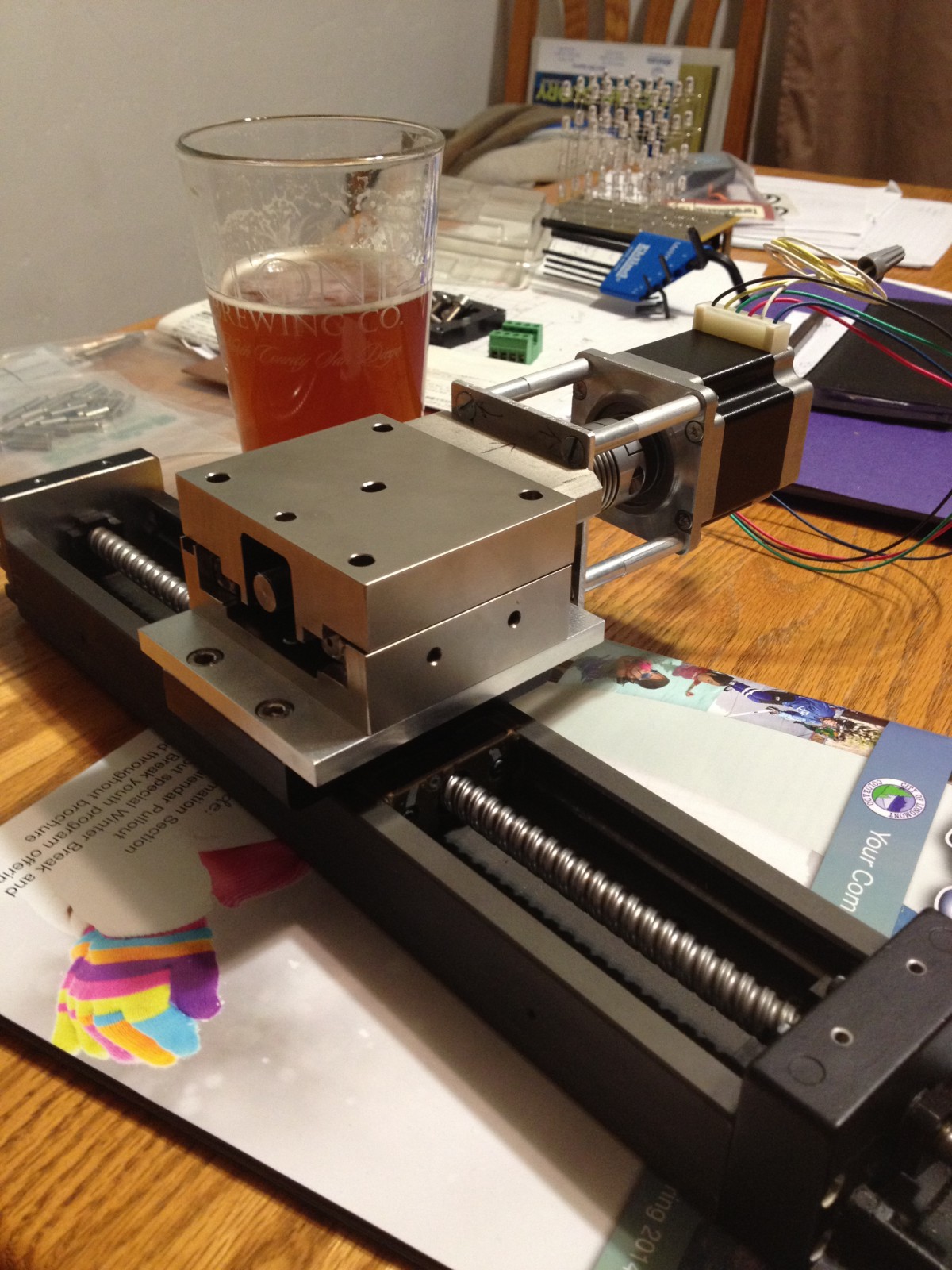
These actuators were not long enough to give me the work area I wanted, but they were so affordable I couldn’t pass them up. I ended up with a work envelope of 8.5″x 8.5″ although a thoughtful approach to the machine design allows me to work in that area on a piece of material 12″ wide and nearly any length. A little more digging around the bay, and I came up with an actuator that works for my z-axis. It has an acme screw and antibacklash nut. It only has a 1.5″ stroke, but that should work for most things I want to do, and again the price was right. Using these integrated actuators saved an immense amount of mechanical design work and greatly reduced the number of individual parts used.
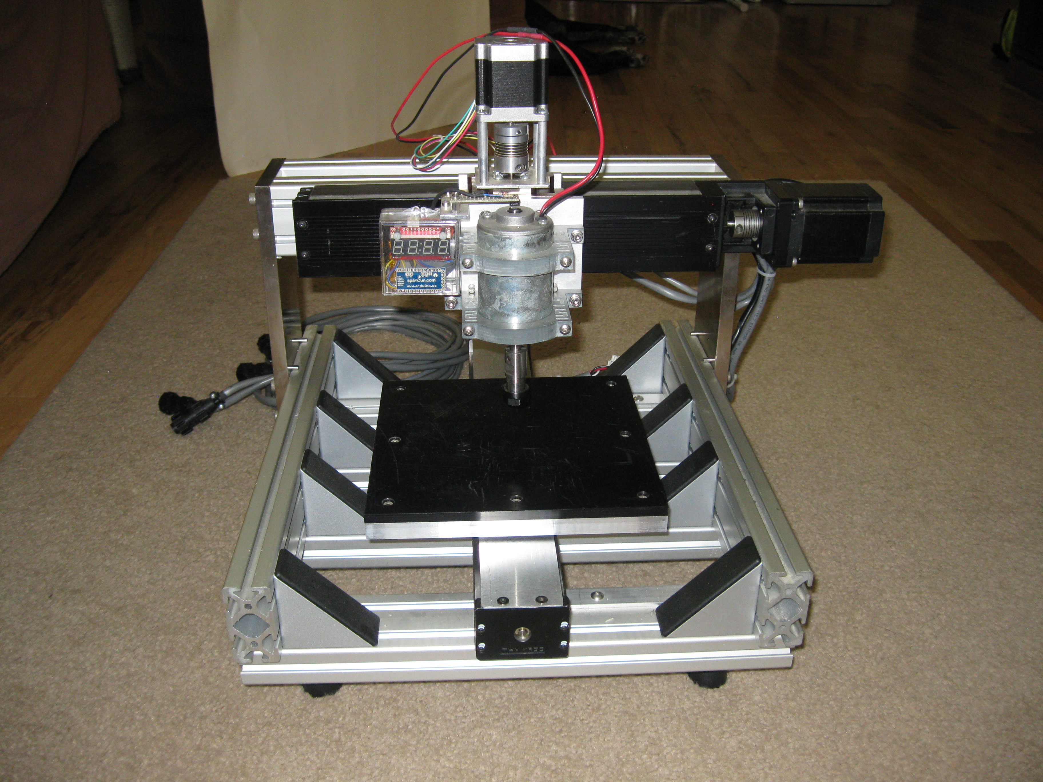
Since GRBL ouputs industry-standard step and direction signals, I already had some suitable stepper motor drives. A quick search of one of my favorite webstores, alltronics.com, produced some very reasonably priced stepper motors that would work with the motor mounts on the actuators I bought. This project was coming together much more quickly that I had anticipated. After a few evenings of designing mounting brackets and adapter plates in Solidworks, I was ready to start the fabrication. I had a bit of help from a machinist friend who made the closely-toleranced adapter plates. The frame is made from common industrial aluminum extrusion. And after a few more evenings of assembly, I had a complete 3-axis gantry built.
I started to work on the electronics next. I mounted the 48 volt power supply, Arduino, and the stepper motor drivers in the case of the PC that would be used to run the mill. Next, I purchased a spindle and collet unit from zentoolworks.com, which works great and also turned out to be the single most expensive component in the build. A few more evenings of researching software, and I decided to use G-Code Sender as the interface between the PC and the Arduino. Now I had a complete working CNC router that I tested with some generic G-Code I found on the net. All I needed at that point was to find and teach myself how to use some open source CAM software so that I could actually start making things.


