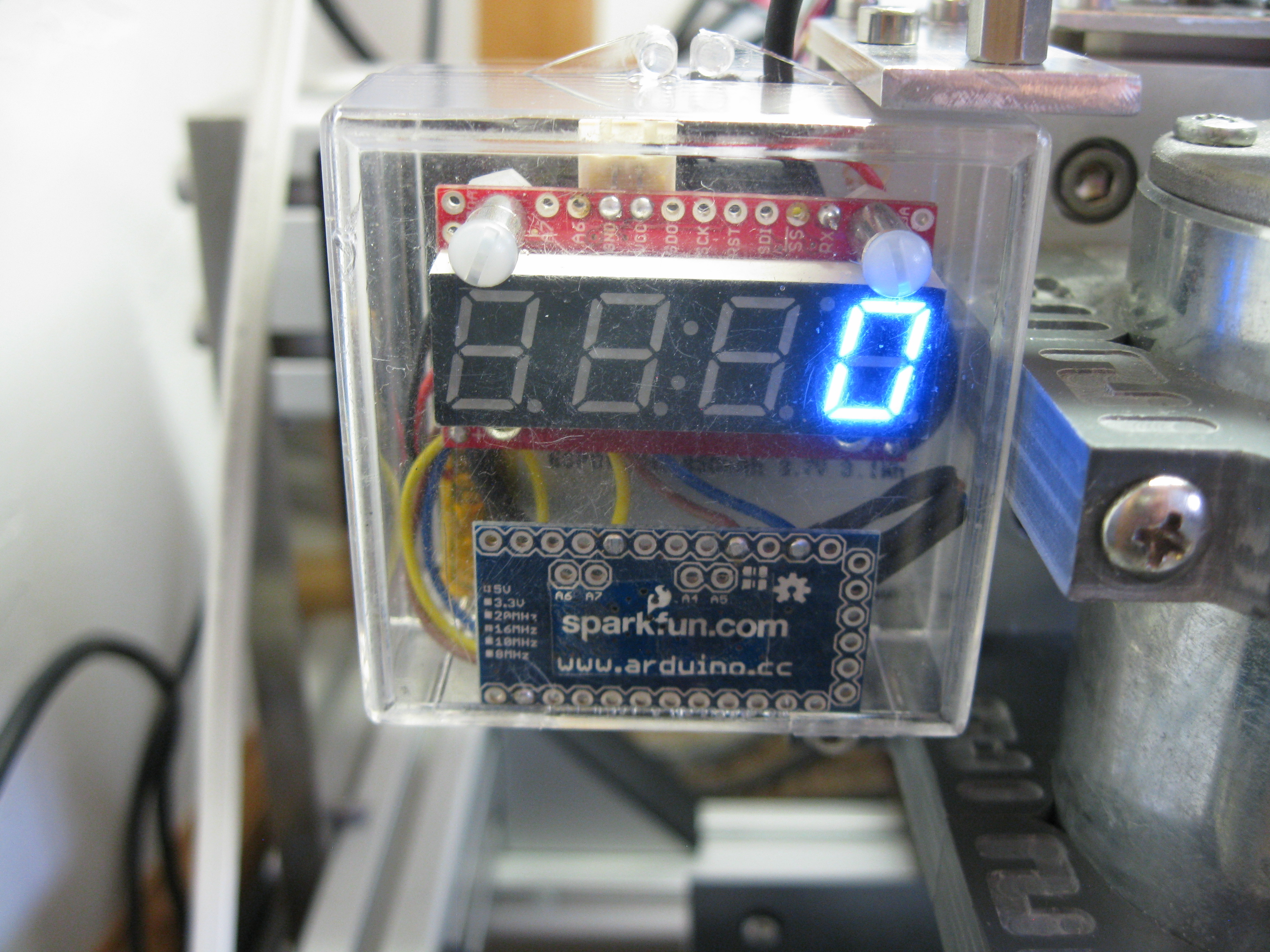
 After I built my CNC router, I did some less-than-scientific empirical testing to determine how aggressively I could cut different materials without causing the spindle motor to bog down. I made a series of test cuts, increasing the cutting depth a little each time until I could hear the spindle slow down. This satisfied me for a while, but the real solution was to put a tachometer on the spindle. This would be an easy project to make and would involve some LEDs, so it would be fun too. A quick shopping trip at my favorite web store sparkfun.com, and I had everything I needed. Looking at the top end of the motor, the shaft protrudes through a bearing to the outside. I used the loveable old QRD1114 optical detector as a sensor and a little black paint to cover half of the protruding motor shaft, so the sensor would have something to see. An Arduino Pro Mini counts the pulses generated by the optical detector, does some simple math, formats the value, and sends it to a Sparkfun 7-Segment Serial Display. A lipo battery powers the circuit. I fabricated a simple aluminum bracket to hold the photo detector above the motor shaft and added some holes to the spindle mounting plate on my CNC machine. Now I just needed a tidy way to mount the electronics to the spindle so the LED display was visible. Inspired by a recent Sparkfun blog post “Everything Is an Enclosure…” I used a simple jewel case that had been sitting out on my workbench; it was just the right size to hold everything.


